×
- Hello
- Login or Register
- Quick Links
- Live Chat
- Track Order
- Parts Availability
- RMA
- Help Center
- Contact Us
- Shop for
- Volvo Parts
My Garage
My Account
Cart
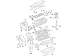
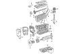
Genuine Volvo S80 Piston
Engine Pistons- Select Vehicle by Model
- Select Vehicle by VIN
Select Vehicle by Model
orMake
Model
Year
Select Vehicle by VIN
For the most accurate results, select vehicle by your VIN (Vehicle Identification Number).
24 Pistons found

Volvo S80 Piston Part Number: 30750274
$166.25 MSRP: $214.69You Save: $48.44 (23%)Ships in 1-2 Business DaysVolvo S80 Piston Part Number: 30750275
$166.25 MSRP: $214.69You Save: $48.44 (23%)Ships in 1-2 Business DaysVolvo S80 Piston Part Number: 30750276
$166.25 MSRP: $214.69You Save: $48.44 (23%)Ships in 1-2 Business DaysVolvo S80 Piston Part Number: 30750892
$166.25 MSRP: $214.69You Save: $48.44 (23%)Ships in 1-2 Business DaysVolvo S80 Piston Part Number: 30750893
$166.25 MSRP: $214.69You Save: $48.44 (23%)Ships in 1-2 Business DaysVolvo S80 Piston Part Number: 30750894
$166.25 MSRP: $214.69You Save: $48.44 (23%)Ships in 1-2 Business DaysVolvo S80 Piston Part Number: 9487401
$166.25 MSRP: $214.69You Save: $48.44 (23%)Ships in 1-2 Business DaysVolvo S80 Piston Part Number: 9487402
$166.25 MSRP: $214.69You Save: $48.44 (23%)Ships in 1-2 Business DaysVolvo S80 Piston Part Number: 9487403
$166.25 MSRP: $214.69You Save: $48.44 (23%)Ships in 1-2 Business Days
Volvo S80 Piston Part Number: 272947
$112.71 MSRP: $133.07You Save: $20.36 (16%)Ships in 1-2 Business DaysVolvo S80 Piston Part Number: 274363
$126.38 MSRP: $149.22You Save: $22.84 (16%)Ships in 1-2 Business DaysVolvo S80 Piston Part Number: 274132
$138.90 MSRP: $163.99You Save: $25.09 (16%)Ships in 1-2 Business DaysVolvo S80 Piston Part Number: 274133
$138.90 MSRP: $163.99You Save: $25.09 (16%)Ships in 1-2 Business Days
Volvo S80 Piston Part Number: 32240862
$136.17 MSRP: $175.85You Save: $39.68 (23%)Ships in 1-2 Business Days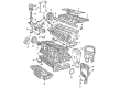
Volvo S80 Piston Part Number: 30731508
$191.48 MSRP: $247.40You Save: $55.92 (23%)Ships in 1-2 Business DaysVolvo S80 Piston Part Number: 30750664
$195.52 MSRP: $252.61You Save: $57.09 (23%)Ships in 1-2 Business DaysVolvo S80 Piston Part Number: 274364
$166.25 MSRP: $214.69You Save: $48.44 (23%)Ships in 1-2 Business DaysVolvo S80 Piston Part Number: 30731509
$166.25 MSRP: $214.69You Save: $48.44 (23%)Ships in 1-2 Business DaysVolvo S80 Piston Part Number: 30731510
$201.06 MSRP: $259.77You Save: $58.71 (23%)Ships in 1-2 Business DaysVolvo S80 Piston Part Number: 30750663
$166.25 MSRP: $214.69You Save: $48.44 (23%)Ships in 1-2 Business Days
| Page 1 of 2 |Next >
1-20 of 24 Results
Volvo S80 Piston
OEM parts are the only choice for top quality and real functionality. They pass strict checks, and they match Volvo's factory specs, so installation is easy. If you need new Piston and you want quality and fit. You will find both here. Our site has a wide range of OEM Volvo S80 parts. The prices are unbeatable, allowing you to get value for money. Each genuine S80 Piston comes with the manufacturer's warranty. That gives you peace of mind. We ship fast to your door. Order today, and enjoy a smooth, no-hassle upgrade with parts that fit right.
Volvo S80 Piston Parts and Q&A
- Q: What steps should be taken before refitting the piston/connecting rod assemblies on Volvo S80?A:Before refitting piston/connecting rod assemblies, make sure the cylinder bores are clean and the Crankshaft and intermediate section are in position. Big end bearing cap No 1 cylinder connecting rod Remove the Big end Bearing Cap From No 1 cylinder connecting rod, take out the original bearing shells and wipe the bearing recesses with a clean, lint-free cloth and keep them spotless. Have new big end bearing cap retaining bolts on hand. Clean the back of the new upper bearing shell, fit it to No 1 connecting rod and put the other shell in the big end bearing cap, ensuring that the one with the black size marker goes to the connecting rod. In the case of 'fractured' type rods and caps, place the shells in the centre without any locating notch. Correctly position the Piston Ring gaps, lubricate the piston and rings with clean engine oil and put on a piston ring compressor, leaving the skirt protruding slightly. Turn the crankshaft to position No 1 big end journal at the Bottom Dead Centre and squirt engine oil on the cylinder walls. Align the No 1 piston/connecting rod assembly so that the arrow on the piston crown is at the timing belt end of the engine or the channel is at the piston cooling jet and gently insert the No 1 piston/connecting rod assembly into the No 1 cylinder bore. Tap the top edge of the ring compressor to ensure it is in contact with the block, and then gently tap with a wooden hammer handle on the piston while guiding the connecting rod big-end onto the crankpin while keeping the pressure on the ring compressor to prevent the rings popping out. If resistance is felt stop immediately to identify and fix the issue without forcing the piston. Make sure that the bearing surfaces are clean and put a uniform amount of clean engine oil on the bearing surfaces (possibly pushing the piston back a bit to expose the bearing surface). Slide the connecting rod back on the big end journal and refit the big end bearing cap, lubricate the bolt threads and fit the bolts and tighten the bolts in two stages to the specified torque. Repeat the procedure for the remaining piston/connecting rod assemblies keeping the back of the bearing shells and recession clean, the correct piston/rod assembly for each cylinder, lubricating the cylinder bores and lubricating the bearing surfaces to be fitted with the caps. After installation, rotate the crankshaft by hand to see if there is binding. For diesel engines, if new pistons, connecting rods or crankshaft are fitted, or a new short engine is fitted, measure the projection of the piston crowns above the surface of the cylinder head at Top Dead Centre to establish the correct head gasket. Fit sump, fix the DTI gauge to the cylinder block, zero it on head gasket mating surface, rest the probe on No 1 piston crown and turn the crankshaft slowly so that maximum projection is measured at Top Dead Centre. Repeat this for the rest of the pistons and note down the measurements, using the largest measurement to work out what type of head gasket you need.


