×
- Hello
- Login or Register
- Quick Links
- Live Chat
- Track Order
- Parts Availability
- RMA
- Help Center
- Contact Us
- Shop for
- Volvo Parts
My Garage
My Account
Cart
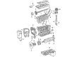
Genuine Volvo V50 Piston Ring
Piston Ring Set- Select Vehicle by Model
- Select Vehicle by VIN
Select Vehicle by Model
orMake
Model
Year
Select Vehicle by VIN
For the most accurate results, select vehicle by your VIN (Vehicle Identification Number).
3 Piston Rings found

Volvo V50 Piston Rings Part Number: 30731512
$61.77 MSRP: $79.76You Save: $17.99 (23%)Ships in 1-2 Business Days
Volvo V50 Piston Rings Part Number: 30750667
$61.77 MSRP: $79.76You Save: $17.99 (23%)Ships in 1-2 Business Days
Volvo V50 Piston Rings Part Number: 31375028
$61.77 MSRP: $79.76You Save: $17.99 (23%)Ships in 1-2 Business Days
Volvo V50 Piston Ring
OEM parts are the only choice for top quality and real functionality. They pass strict checks, and they match Volvo's factory specs, so installation is easy. If you need new Piston Ring and you want quality and fit. You will find both here. Our site has a wide range of OEM Volvo V50 parts. The prices are unbeatable, allowing you to get value for money. Each genuine V50 Piston Ring comes with the manufacturer's warranty. That gives you peace of mind. We ship fast to your door. Order today, and enjoy a smooth, no-hassle upgrade with parts that fit right.
Volvo V50 Piston Ring Parts and Q&A
- Q: How should the end gaps of piston rings be checked and fitted to ensure proper assembly on Volvo V50?A:At this stage it is presumed that the pistons have been correctly assembled to their respective connecting rods and that their piston ring-to-groove clearance has been checked. Before fitting the rings to the pistons the end gaps should be checked with the rings fitted in the cylinder bores. Lay out piston assemblies and new ring sets to ensure that the components are kept together during and after end gap checking. Place the cylinder block on the work surface, on its side, so that it is possible to access the top and bottom of the bores. Take the No 1 piston top ring and insert it into the top of the first cylinder pushing it down the bore by using the top of the piston to help make sure the ring stays square with the cylinder walls, it should be near the bottom of the cylinder bore at the lower limit of ring travel. Note that the top and second compression rings are different, the second being recognisable by the step on the lower surface. With feeler blades measure the ring gap and repeat the process at the upper limit of the cylinder bore and compare the results to the specification. If new rings are being fitted, it is unlikely that the end gaps will be too small but if a measurement is found to be undersize, this needs to be corrected to avoid the risk of the end of the rings coming into contact with each other during engine operation, leading to possible engine damage. Ideally it is best to fit new piston rings with the correct end gap, but when it is impossible, the end gaps can be enlarged by carefully filing the ring ends with a fine file. It is also unlikely that the end gap will be too large, if gaps are too large check that the correct rings for the engine and cylinder bore size are being used. Repeat the checking procedure for each ring in the first cylinder and then for the rings in the remaining cylinders making sure that rings, pistons, and cylinders are matched up. Once the ring end gaps have been checked and corrected if necessary the rings can be fitted to the pistons using the same technique as for removal but starting with the bottom scraper ring and working up. Note the markings of the text on one side of the top and bottom rings which should face upwards when fitted, whilst the middle ring, which is bevelled or stepped, should have the bevel or step facing downwards. Don't expand the compression rings too much to prevent breakage, or follow any instructions that came with the new piston ring sets, as different manufacturers may have different instructions. Do not confuse the top and second compression rings, as they have different cross-sections and when all the rings are in position, arrange the gaps in the rings at 120deg from one another except for the 3-part oil scraper ring where the two plain rings should be 90deg from each other.


