×
- Hello
- Login or Register
- Quick Links
- Live Chat
- Track Order
- Parts Availability
- RMA
- Help Center
- Contact Us
- Shop for
- Volvo Parts
My Garage
My Account
Cart
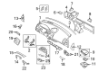
Genuine Volvo Ignition Lock Cylinder
Ignition Key Lock Cylinder- Select Vehicle by Model
- Select Vehicle by VIN
Select Vehicle by Model
orMake
Model
Year
Select Vehicle by VIN
For the most accurate results, select vehicle by your VIN (Vehicle Identification Number).
11 Ignition Lock Cylinders found


Volvo Ignition Lock Cylinder Part Number: 8626375
$204.77 MSRP: $264.56You Save: $59.79 (23%)Ships in 1-2 Business DaysProduct Specifications- Other Name: Column Lock; Cylinder & Key

Volvo Ignition Lock Cylinder Part Number: 8679170
$235.56 MSRP: $306.72You Save: $71.16 (24%)Ships in 1-2 Business DaysProduct Specifications- Other Name: Lock Cylinder

Volvo Ignition Lock Cylinder Part Number: 31253385
$376.88 MSRP: $490.74You Save: $113.86 (24%)Ships in 1-2 Business DaysProduct Specifications- Other Name: Column Lock; Cylinder & Key, Lock Housing


Volvo Cylinder & Keys Part Number: 8626325
$376.88 MSRP: $490.74You Save: $113.86 (24%)Ships in 1-2 Business DaysProduct Specifications- Other Name: Lock Cylinder; Ignition Lock Cylinder; Cylinder & Key

Volvo Ignition Lock Cylinder Part Number: 31253392
$447.56 MSRP: $582.77You Save: $135.21 (24%)Ships in 1-2 Business DaysProduct Specifications- Other Name: Lock Kit; Lock Housing


Volvo Ignition Lock Cylinder Part Number: 30753443
$374.88 MSRP: $446.28You Save: $71.40 (16%)Ships in 1-2 Business DaysProduct Specifications- Other Name: Lock Kit; Cylinder & Key

Volvo Ignition Lock Cylinder Part Number: 9133364
$235.56 MSRP: $306.72You Save: $71.16 (24%)Ships in 1-2 Business DaysProduct Specifications- Other Name: Column Lock
Volvo Ignition Lock Cylinder Part Number: 6819269
$290.86 MSRP: $375.79You Save: $84.93 (23%)Ships in 1-2 Business DaysProduct Specifications- Other Name: Lock Kit 2509
Volvo Cylinder & Keys Part Number: 9126768
$253.57 MSRP: $301.87You Save: $48.30 (16%)Ships in 1-2 Business DaysProduct Specifications- Other Name: Lock Kit; Ignition Lock Cylinder; Cylinder & Key

Volvo Cylinder & Keys Part Number: 30803270
Product Specifications- Other Name: Lock Cylinder; Ignition Lock Cylinder; Cylinder & Key

Volvo Ignition Lock Cylinder Part Number: 30887387
Product Specifications- Other Name: Column Lock; Lock Housing, Steering Lock
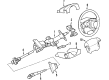
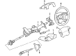
Volvo Ignition Lock Cylinder
Volvo Ignition Lock Cylinder ensures that every ride is secure whether it involves the correct key and energizing important circuits for the car or locking the steering wheel when removed from the vehicle preventing thieves from hot wiring the vehicle. Volvo has established itself as a globally respected maker of vehicles that prioritize safety first, from developing the three-point seat belt to perfecting the clean Scandinavian design to keep dashboards simple and distractions at a minimum. The company began in 1927 in Gothenburg and now makes cars, trucks, and buses that share common traits of solid construction, advanced braking, and a growing range of efficient electric and hybrid powertrains, indicative of Volvo's balance between ruggedness and innovation. Families and commuters enjoy the confident driving and comfortable cabins that make long trips more enjoyable, whereas environmental targets drive Volvo to reduce emissions without compromising performance. The Ignition Lock Cylinder continues that safety legacy throughout the lineup and combines tough metal tumblers with intelligent electronic coding so that only the matched chip makes allowance for component, on, and start positions. Because the Ignition Lock Cylinder is directly tied into the engine computer, thieves cannot just twist wires and give owners peace of mind in driveways, parking lots, and city streets. Smooth key insertion and regular attention mean the Ignition Lock Cylinder works flawlessly and because it is now universal in the brand, every Volvo is blessed with reliable starts, steady electrical delivery, and rock-solid theft deterrence.
Trust OEM Ignition Lock Cylinder for quality that holds up. These parts use top-tier materials to keep your ride running smooth. Because they match exact Volvo specs, you get a flawless fit and a hassle-free install every single time. No more fighting with parts that just won't line up. It is easy to search our massive stock of genuine Volvo options at prices you will really like. Every part comes with a real manufacturer's warranty and a simple return policy. Plus, we ship fast to get your order to you. Shop with confidence and give your Volvo the reliability it deserves.
Volvo Ignition Lock Cylinder Parts and Q&A
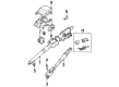
- Q: How to replace the ignition lock cylinder and ignition switch assembly on Volvo 960?A:The ignition lock cylinder/switch is an integral unit in which the lock cylinder rotates within the switch assembly, making contact with terminals which select which circuit to energize, and the replacement of the components must be done as an assembly. For the 240 Series, the ignition lock cylinder is mounted on the steering column and has a steering wheel lock to prevent theft of the vehicle, which requires the steering column assembly to be removed to access. Start with disconnecting the negative battery cable (tapping the end once with duct tape) and remove the air bag assembly, steering wheel and contact reel. If necessary, pull the cover from the lower steering shaft joint, loosen the upper bolts in the joints and pull down the lower steering shaft to free the upper joint. Remove the upper and lower steering column covers, disconnect the wiper control connector and remove the retaining bolts for the wiper and indicator controls holder. Lift the holder over the steering shaft, noting the position of the lead from the indicator switch, and remove the connector from the starter switch if necessary. Remove the lower retaining bracket of the steering column, seal in the firewall and defroster hose of the heater unit and tap the shearing bolts to slide it out. Carefully remove the steering column with the steering lock with it, avoiding catching it on the firewall as it passes through it. Mount the steering column in a vise, break off the washers from the shearing bolts and remove them with channel locks. Press the ignition lock assembly from the steering column with an appropriate drift and counterhold tool, insert the key in the ignition lock and rotate it, then press the new ignition lock assembly into the steering column, making sure to fit it into the right position. Remove the key, and check the lock barret locks the steering shaft, and check the integrity and length of the collapsible coupling. Install the plastic guides and position the steering column, tightening the bolts, but not shearing them. Install rubber grommets, lower retaining bracket and cover the firewall rubber seals with petroleum jelly and fit the seal on the steering column. Tighten the upper bolts and then the lower retaining bolts and reconnect the ignition lock connector. Mount the universal joint to the shafts of the upper steering column, install the locking pins, measure the distance between the upper steering shaft joint and the lower steering shaft. Install the holder for the combination switch control and connect the leads and ground the lead to a retaining bolt. Install the upper and lower steering column covers Set the contact reel to zero position, the front wheels should be straight, and the contact reel bracket should be installed. Reconnect and position the lead and the steering wheel has been installed and the steering wheel nut has been tightened. Finally, attach the negative battery cable and test the SRS lamp for any fault codes. For models other than 240 Series, position the front wheels in the straight-ahead position, disconnect the negative battery cable, remove the air bag assembly, the steering wheel, contact reel assembly, combination switch, and steering column rake adjustment lever. Remove the parking plate around the steering tube, disconnect the ignition lock connector, turn the ignition switch to position f, press down the tumblers in the cylinder and remove the lock assembly. To install, place the steering lock assembly, turn the ignition switch to position I, and press down the tumblers and install the assembly of the lock, and the combination switch, the contact reel, the steering wheel, and the air bag. Finally, reattach the negative battery cable and examine the vehicle operation and SRS system for fault codes.
Related Volvo Parts
 Volvo Air Bag
 Volvo Instrument Cluster
 Volvo Fuse Box
 Volvo Parking Sensors
 Volvo Power Seat Switch
 Volvo Air Bag Sensor
 Volvo Brake Light Switches
 Volvo Cruise Control Module
 Volvo Exhaust Nut
 Volvo Hazard Warning Switches
 Volvo Junction Boxes
 Volvo Mirror Switch
Browse by Model
740 Ignition Lock Cylinder 960 Ignition Lock Cylinder C30 Ignition Lock Cylinder C70 Ignition Lock Cylinder S40 Ignition Lock Cylinder S60 Cross Country Ignition Lock Cylinder S60 Ignition Lock Cylinder S70 Ignition Lock Cylinder S80 Ignition Lock Cylinder S90 Ignition Lock Cylinder V40 Ignition Lock Cylinder V50 Ignition Lock Cylinder V60 Cross Country Ignition Lock Cylinder V60 Ignition Lock Cylinder V70 Ignition Lock Cylinder V90 Ignition Lock Cylinder XC60 Ignition Lock Cylinder XC70 Ignition Lock Cylinder XC90 Ignition Lock Cylinder